
Manufacturing & Quality
Mine Ventilation Fan Manufacturing & Quality Control
At BOFENG, quality control follows the fan from approved drawings and incoming materials through fabrication, assembly and factory testing. The sections below explain the checks and records used at each stage.
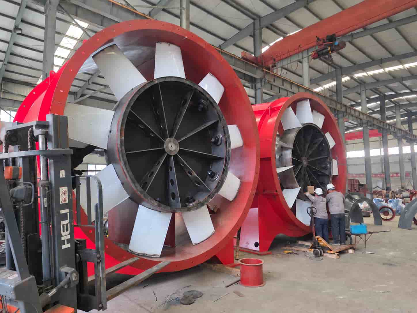
The main photograph shows blade installation and adjustment on large axial mine ventilation fans. Other photographs and factory footage on this page show impeller balancing, electrical test setups and laboratory test ducts, with the accompanying text explaining the checks and records used during manufacturing and testing.
Need a project-specific inspection or test plan?
Send the required airflow, pressure, power supply, installation arrangement, operating environment, requested measurements and document list before production. The inspection scope can then be defined together with the fan configuration.
Manufacturing controls
Quality Control Is Built Into the Production Route
Approved drawings, the bill of materials and the fan-series inspection procedures guide production. Incoming materials, work in progress and the completed fan are checked against the relevant requirements.
Measuring equipment is managed under the company's inspection procedures. Production and test records connect the supplied fan configuration with the checks performed and the results recorded.
Inspection scope: The manufacturing checks below focus on axial mine ventilation fans. Required inspections follow the technical requirements and inspection procedures for the fan series; they do not depend on a separate customer request. Additional performance-test points, special coating inspections and witnessed tests are defined in the project agreement. Explosion-protected configurations also require checks of the approved electrical components and corresponding certification documents.
Manufacturing and Testing Process at a Glance
- Order review and controlled production documents
- Incoming material and component verification
- Layout, cutting and component forming
- Welding, dimensional correction and re-inspection
- Impeller assembly, blade setting and balancing
- Surface preparation and coating
- Final assembly, alignment and clearance adjustment
- Electrical and pre-start checks
- Factory run test
- Voltage and current measurement
- Airflow and pressure testing with laboratory data acquisition
- Test records and witnessed FAT where agreed
- Control of nonconforming parts and test results
- Final release, marking, documentation and packing
These checks are connected: cutting dimensions, weld distortion, blade setting and running clearances can affect later assembly and operation. Nonconforming parts and test results are controlled whenever they are found; item 13 applies throughout production and testing, not only at final inspection.
Order review & incoming checks
Drawings, Materials and Components
01Order Review and Controlled Production Documents
Production begins with a review of the technical offer, order requirements and released manufacturing documents. The factory needs a clear definition of the required fan series, airflow, pressure, motor power, voltage, frequency, installation arrangement, ventilation duty, operating environment and supplied accessories.
The review should also identify project-specific requirements before fabrication starts, including special materials, corrosion protection, explosion-protection requirements, direction of rotation, inlet and outlet connections, monitoring accessories, inspection hold points, witnessed testing and the final document package. Approved drawings and the bill of materials remain the controlling references on the workshop floor. A later change to a key component or configuration must be reviewed before it is introduced into production.
02Incoming Material and Component Verification
Incoming materials and components are checked against the released documents for the supplied configuration. These may include steel plate, motors, bearings, shafts, couplings, fasteners and ordered accessories. The checks relevant to each item cover:
- material specification, thickness, quantity and visible condition;
- motor model, rated power, voltage, frequency, speed and mounting arrangement;
- bearing, shaft, coupling or transmission components;
- flange dimensions, mounting interfaces and connection requirements;
- guards, silencers, flexible connectors and monitoring accessories;
- special coating, corrosion-resistance and explosion-protection requirements.
Identification is important on non-standard orders. Two parts may look similar while having different flange dimensions, hole patterns or mounting positions. Keeping each part connected to the released drawing reduces the risk of a mix-up later in fabrication or assembly.
Fabrication control
From Cut Plate to a Checked Casing
03Layout, Cutting and Component Forming
Steel plate is laid out and cut for the casing, inlet, diffuser, flanges, supports, motor mounting parts and other fabricated sections. The workshop checks part quantity, identification, key dimensions and edge condition. Burrs, slag and sharp edges are removed where required before forming and welding.
Cut parts are then formed into the required cylindrical, conical or structural shapes. Casing roundness, flange position and trial fit are checked before final welding. A casing may meet its nominal diameter and still create an assembly problem if the adjoining flange faces or bolt holes do not align. Early fit checks reduce correction work after coating or final assembly.
04Welding, Dimensional Correction and Re-inspection
Formed sections are positioned and welded to create the fan casing, base, supports, inlet, diffuser and other structural assemblies. During fitting and welding, the team checks the interfaces needed for later assembly, including flange position, support location, mounting faces and critical dimensions.
Welding heat can pull a correctly fitted part out of line as the assembly cools. Key dimensions are therefore checked again after fabrication. Where correction is required, hydraulic pressing or another controlled method may be used to restore roundness, alignment or fit. The corrected part is then measured again before it moves to the next stage.
Routine visual inspection looks for weld continuity, visible cracks, incomplete areas, excessive deformation, slag and spatter. Additional non-destructive examination follows the requirements stated in the drawing, technical agreement or inspection plan.
Impeller & rotating assembly
Impeller Assembly, Blade Setting and Dynamic Balancing
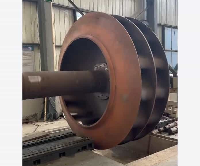
The impeller is inspected separately because it is the principal rotating component. Depending on the design, the checks include blade orientation, blade position or setting, hub condition, fastener or weld condition, visible deformation and conformity with the applicable drawing. On adjustable-blade designs, consistent blade setting is essential before the rotating assembly is accepted.
Impeller balancing follows the production and inspection requirements for the fan series. The balance record identifies the fan or impeller. When correction is needed, the rotating assembly is rechecked against the specified acceptance criteria and the result is recorded.
Balancing and vibration checking are not the same operation
Balancing corrects mass distribution in the rotating assembly. The factory run checks the assembled fan, including vibration measurements required by the fan-series inspection procedure. Alignment, running clearance, bearings, fasteners, support conditions and electrical supply can also affect vibration; an impeller balance result does not replace the assembled-fan check.
Surface preparation & finish
Surface Preparation and Coating
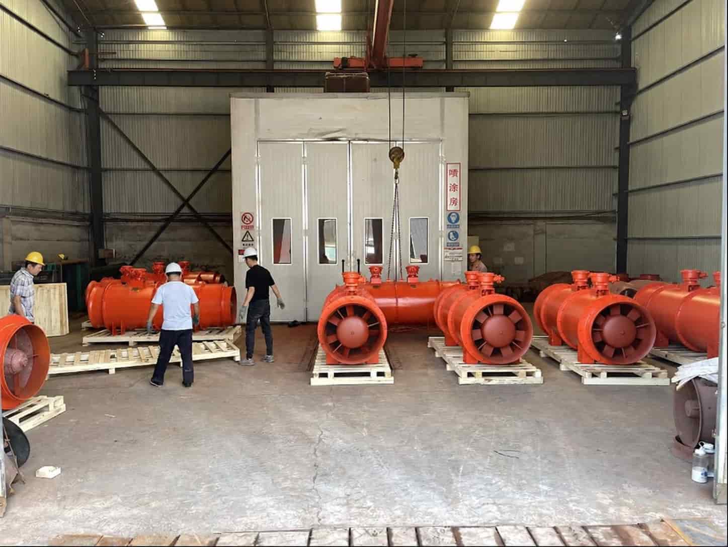
Oil, loose rust, weld spatter, dust and other contamination are removed according to the coating requirement. Primer, intermediate treatment and finish coating are applied according to the standard factory finish or the project-specific coating system. Depending on the structure, coating may be completed in stages before and after final assembly.
The main fabrication and dimensional checks should be completed before final coating. After painting, inspection covers color, coverage, missed areas, visible runs, contamination and handling damage. Fans intended for humid, corrosive, coastal or chemical environments may require a named coating system, surface-preparation grade or dry-film-thickness requirement. These details should be written into the order documents rather than left as a verbal request.
Assembly and start-up preparation
Check the Complete Assembly
07Final Assembly, Alignment and Running-Clearance Adjustment
Final assembly follows the specified fan configuration and supply scope. Checks cover the casing, motor, impeller and the fitted drive components, connections, guards and accessories. The relevant checks include:
- correct motor model and mounting position;
- correct impeller installation and rotation direction;
- bearing installation and lubrication condition, where applicable;
- shaft or coupling alignment, where applicable;
- impeller-to-casing running clearance;
- fastener tightening and locking measures;
- guards, supplied accessories and direction markings;
- free manual rotation before electrical power is applied.
Counter-rotating fans require an additional stage-sequence and rotation check. The two impellers must be installed in the correct order and direction. A stage-order or rotation error should be found during assembly and factory operation, not after delivery to the mine.
08Electrical and Pre-start Checks
Before the first powered run, the motor nameplate, rated voltage and frequency, supply and connection arrangement are checked against the approved configuration. Insulation and other electrical checks follow the fan-series inspection procedure and project requirements. For explosion-protected fans, the approved electrical configuration and associated component documents are also reviewed.
The fan is then secured for operation. The rotating path must be clear, guards and main fasteners must be checked, cables must be arranged safely, and personnel must remain outside the operating hazard area. These checks are completed before the fan is energized.
Factory operation & electrical measurement
Running and Electrical Tests
09Factory Run Test
The factory run test checks the assembled fan's starting and running condition. It forms part of the required final inspections for the supplied fan configuration.
Checks cover starting, rotation, impeller rubbing, unusual noise, looseness and motor or bearing condition. Vibration is measured and recorded where required by the fan-series inspection procedure, with the fan configuration and test conditions identified. Abnormal findings are investigated and the affected check is repeated after correction.
10Voltage and Current Measurement
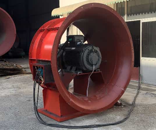
Voltage and current are measured while the fan is running. These checks apply to main and auxiliary fans and can also be carried out in the fan laboratory.
The electrical test record identifies the fan, motor configuration, supply condition, operating condition and measured voltage and current. These readings document the electrical conditions and do not replace airflow and pressure measurements.
Required measurements and acceptance criteria are set for the selected fan configuration.
Aerodynamic performance testing
Airflow and Pressure Testing in the Fan Laboratory
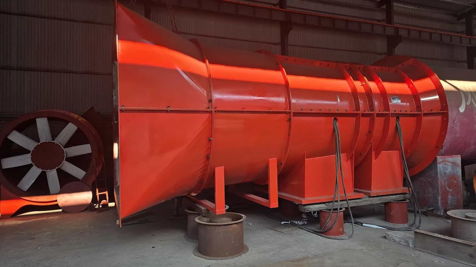
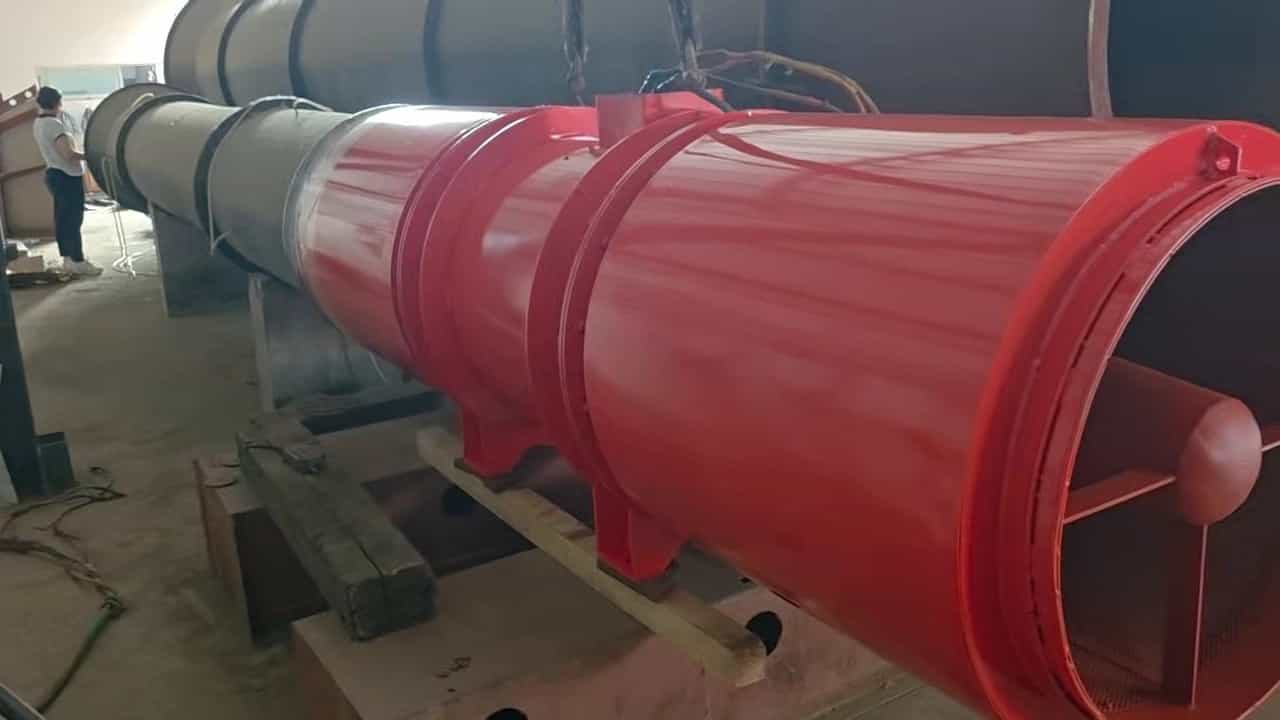
BOFENG measures airflow and pressure using a laboratory test-duct setup. The photographs show main and auxiliary fans connected to their respective test ducts, followed by the measurement and data-acquisition screen.
Data acquisition is part of the performance test: the laboratory system displays and records the measurements taken at the specified operating points.
Main Fan Airflow and Pressure Test
Auxiliary Fan Airflow and Pressure Test
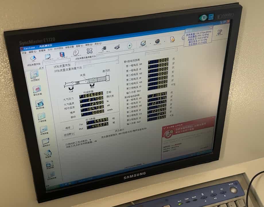
Laboratory Measurement and Data Acquisition
The fan laboratory measures airflow and pressure and can also measure voltage and current while the fan is running. Its measurement and data-acquisition system displays the test-duct schematic together with operating, environmental and electrical parameters.
The performance-test report identifies the fan configuration, test setup, operating conditions and static or total-pressure basis. It records airflow and pressure at the required test points, together with voltage and current readings included in the test scope. Fan speed, performance-curve coverage and acceptance criteria are specified in the test plan.
Inspection scope & witnessed testing
Test Records and Witnessed Factory Acceptance Testing
The table below distinguishes running checks, electrical measurements, performance testing and site commissioning. For a witnessed Factory Acceptance Test (FAT), the buyer or a third party observes the agreed checks and reviews the required records.
| Inspection or test | Main purpose | Measurements or observations | Record and scope |
|---|---|---|---|
| Factory run test | Check the assembled fan's starting and running condition. | Starting, rotation, rubbing, unusual noise, looseness, motor or bearing condition, and vibration measurements required by the fan-series procedure. | Run-test record with fan identification, test conditions and required inspection results, including applicable vibration results. |
| Voltage and current testing | Check electrical conditions while the fan is operating. | Voltage and current at the identified supply and operating condition. | Electrical readings linked to the fan, motor configuration and test condition. |
| Laboratory airflow and pressure testing | Measure the fan's aerodynamic performance under defined conditions. | Airflow and pressure at specified test points; voltage and current can also be measured. | Performance report identifying the fan, test conditions, pressure basis and required results, with curve data as specified. |
| Witnessed FAT | Enable the buyer or a third party to witness agreed checks. | Specified inspections, run tests, electrical or performance measurements, and document review. | Witness record covering the agreed test items, acceptance criteria and results. |
| On-site commissioning or acceptance | Check the fan after installation in the ventilation system. | Installed operating condition, controls and site measurements. | Site commissioning or acceptance record, separate from factory test records. |
Photographs document the equipment and test setting. The signed inspection or test report records the measured results and acceptance decision for the identified fan.
Final inspection & documentation
Inspection Records and Delivery
13Control of Nonconforming Parts and Test Results
Nonconforming materials, components and completed fans are identified and separated from accepted items for review. This control applies during incoming checks, fabrication, assembly and testing.
Depending on the finding, the item is reworked, repaired, replaced or rejected. The relevant inspection or test is repeated after correction. The record documents the finding, action taken and verification result.
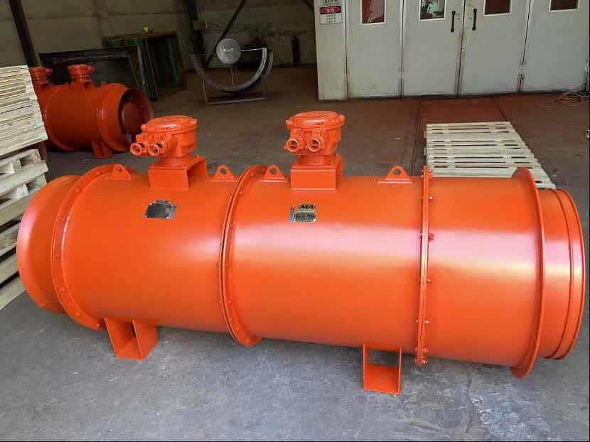
14Final Release, Marking, Documentation and Packing
After the required inspections and tests have been completed, the fan receives a final release check. The review covers the coating, nameplate, serial or product identification, rotation and airflow direction markings, guards, supplied accessories and packing scope.
The inspection record identifies the fan model, serial number, motor configuration, inspection items, results and acceptance decision, together with the inspector and date.
The supplied document set follows the fan-series requirements and the agreed supply scope. It may include:
- product certificate or final inspection record;
- motor certificate and nameplate information;
- impeller balancing record, where applicable;
- factory run test record, with vibration measurements where required;
- voltage and current measurement record;
- airflow and pressure test report, with performance-curve data as required;
- FAT record when witnessed testing was agreed;
- explosion-protected component documents, where applicable;
- installation, operation and maintenance instructions;
- packing list and supplied-accessory list.
Large main fans may be shipped in separate sections. Each section, loose component and package should be clearly identified so the site team can match the inlet, fan sections, diffuser, accessories and fasteners during installation.
Before ordering
What Buyers Should Confirm Before Ordering
- Required duty: airflow, pressure and its static or total-pressure basis, operating range and fan speed.
- Power supply: voltage, frequency, phase and any starting or control requirements.
- Inspection and testing scope: the fan-series inspections, run tests, required vibration measurements and any additional project checks.
- Electrical test record: required voltage and current results, the test condition and any additional specified measurements.
- Laboratory test coverage: test points, fan speed, static or total-pressure basis, curve coverage and any specified voltage and current readings.
- Witnessing: whether the buyer or a third party will witness the FAT in person or remotely.
- Acceptance criteria: test method, tolerances, instruments and report format.
- Documents: certificates, drawings, balancing records, test reports, manuals and packing records.
Agreeing these items with the order makes the inspection scope, acceptance criteria and delivery documents clear to both teams.
Questions & answers
Frequently Asked Questions
Which inspections are included with my fan?
The technical requirements and inspection procedures for the fan series determine the required checks. The quotation and order review specify the inspection scope, performance-test coverage, any additional checks and the documents included in the supply.
Can the fan laboratory also measure voltage and current?
Yes. The laboratory measures airflow and pressure and can also measure voltage and current while the fan is running. The electrical readings are recorded with the motor configuration, supply condition and operating condition when included in the test scope.
What inspection and test documents can be supplied?
The document list can include product and motor records, applicable balance and vibration records, run-test and electrical results, airflow and pressure reports, instructions and packing lists. The records supplied with the fan follow the series requirements and the agreed order scope.
How are balance and vibration acceptance criteria set?
The criteria follow the technical requirements and inspection procedure for the selected fan series. Impeller balance and assembled-fan vibration are assessed separately, using the limits and measurement conditions specified for that configuration.
Can I arrange witnessed factory acceptance testing?
Include buyer or third-party witnessing requirements in the technical agreement. The test items, operating conditions, acceptance criteria, witness method and required reports are agreed before the test date.
What information is needed for an inspection and testing review?
Send the required airflow, pressure and its basis, power supply, installation arrangement and operating environment. Add any specified test points, witnessing requirements, acceptance criteria and document list. Explosion-protected projects should also state the required certification and component documents.
Does factory testing replace site commissioning?
No. Factory tests record the fan under defined test conditions. Site duct or roadway resistance, leakage, foundations, alignment, electrical supply, controls and the ventilation network affect installed operation. Site commissioning and acceptance remain separate activities.
Project review
Request a Fan Selection and Testing Review
Send the required airflow, pressure, power supply, installation layout, operating environment and test-document requirements. BOFENG can review a suitable fan series and define the proposed inspection and testing scope in the technical quotation.