In underground environments with explosion risk, anti-spark performance depends on more than motor protection alone. It also depends on how the fan structure is designed, how clearances between rotating and stationary parts are controlled, and how suitable materials are applied at key positions. This article focuses on anti-spark design in auxiliary mine fans, with particular attention to the silumin impeller, the silumin spark protection ring, and the structural considerations that support safe underground operation.
In practical underground auxiliary ventilation applications, a local mine fan may work under dust, humidity, vibration, repeated relocation, and changing system resistance. Under these conditions, anti-spark treatment should not be treated as an isolated feature. It should be considered as part of the overall engineering design of the fan, together with impeller arrangement, structural rigidity, running clearance, and the operating environment. For product-oriented information on coal mine local auxiliary explosion-proof fans, see our related product page.

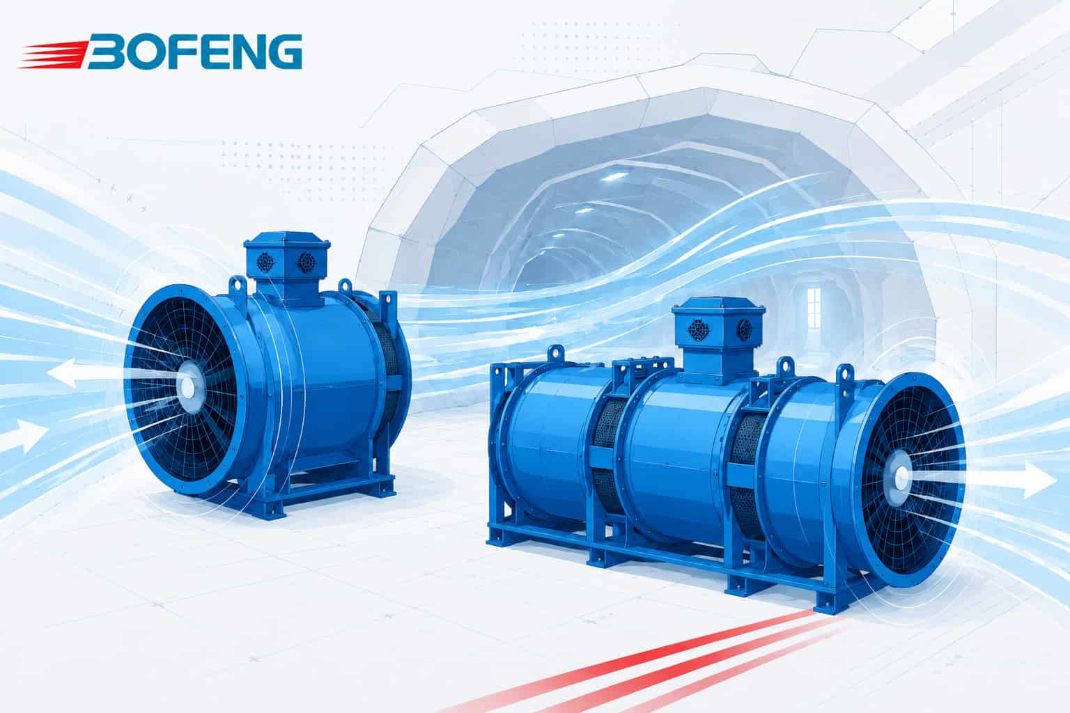
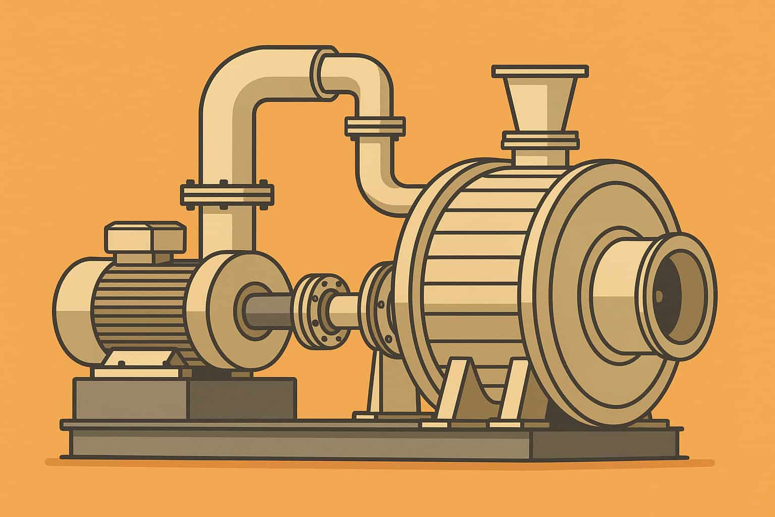
Image 1: Overall fan appearance of a Bofeng-produced local mine fan, provided here as a manufacturer reference for the external configuration used in underground auxiliary ventilation.
Why Anti-Spark Design Matters
Key Factors That Affect Anti-Spark Performance in Auxiliary Mine Fans
In practical underground applications, anti-spark performance depends on several design and operating factors working together. The table below gives a quick view of the main points that should be checked when evaluating an auxiliary mine fan for explosion-risk conditions.
| Factor | Why It Matters | What to Check |
|---|---|---|
| Impeller material | Material selection affects spark risk, rotating mass, and balance behavior. | Material type, operating speed, balance quality, and suitability for the required duty. |
| Spark protection ring | A properly arranged ring can help reduce spark risk if abnormal contact occurs. | Ring material, installation position, wear condition, and fit within the fan assembly. |
| Running clearance | Unstable or insufficient clearance may increase friction risk between rotating and stationary parts. | Assembly tolerance, shaft runout, casing deformation, and clearance consistency during service. |
| Bearing stability | Poor bearing condition can lead to vibration, misalignment, or unexpected contact. | Bearing quality, lubrication condition, support rigidity, and maintenance status. |
| Casing rigidity | Weak structural support may allow deformation under transport, relocation, or operation. | Casing strength, frame support, duct connection stress, and service environment. |
| Installation accuracy | Improper installation can reduce the reliability of the intended anti-spark design. | Alignment, base condition, duct connection method, and vibration after installation. |
Anti-spark design is an important engineering consideration in local mine fans used in underground conditions with explosion risk. It is not limited to the motor alone. It also involves material choice, internal structural arrangement, running clearance control, shaft support, vibration behavior, and the reduction of spark risk if abnormal contact occurs during service. For this reason, anti-spark treatment is best understood as part of the core design logic of the fan rather than as a minor addition after the main structure has already been decided.
The Role of the Silumin Spark Protection Ring
One of the key anti-spark elements discussed in this type of fan structure is the silumin spark protection ring. Public technical references support the broader use of non-sparking materials and structural anti-spark measures in fans intended for potentially explosive atmospheres. Russian technical texts for fan design in potentially explosive atmospheres include material requirements for rotating and stationary parts, allowable material pairings, clearance control, and illustrated examples of anti-sparking construction such as spark-protected rings, copper inserts, and other non-sparking elements. AMCA guidance for spark-resistant construction also states the broader principle of a nonferrous impeller and a nonferrous ring. In the Bofeng example discussed here, a silumin spark protection ring is used as part of that anti-spark design approach. In suitable configurations, this ring is arranged as part of the fan assembly to help reduce spark risk if unexpected contact occurs between rotating and stationary components. Its effectiveness depends not only on the material itself, but also on how it works together with the surrounding structure, including casing geometry, shaft alignment, bearing condition, and the overall tolerance strategy of the rotating assembly.
Why a Silumin Impeller May Be Considered
A related design option is the use of a silumin impeller in selected applications. When assessed as part of the complete rotating system, a silumin impeller may support anti-spark design while also contributing to weight control and rotating balance. In underground auxiliary ventilation equipment, rotating mass influences startup behavior, vibration response, bearing load, and long-term mechanical stability. Because of this, impeller material should always be reviewed together with the wider structural and operating requirements of the fan.

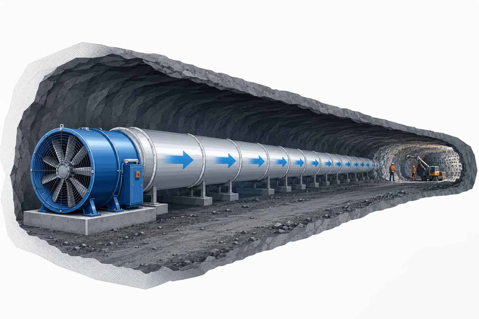
Image 2: Bofeng-produced silumin impeller component, shown here as a sample rotating part used in the discussion of anti-spark local mine fan design.
Structural Control Behind Anti-Spark Performance
Material choice alone does not guarantee anti-spark performance. Running clearance, casing rigidity, shaft alignment, bearing stability, vibration control, installation accuracy, and service conditions all affect whether the intended safety performance can be maintained in real underground operation. Even when suitable materials are selected, poor structural discipline can still create conditions that increase friction risk, instability, or abnormal contact.
The engineering drawing below helps show how anti-spark design should be understood within the full fan assembly. The labeled positions include the inlet collector, impellers, guide vanes, main drive, silencer, outlet connector, working area, and the explosion-proof ring. This makes it clear that anti-spark treatment is linked to the broader structural arrangement of the fan, not just to one isolated component. In the drawing, item 9 identifies the explosion-proof ring, which in this design forms part of the anti-spark arrangement.
Russian public technical texts for fans in potentially explosive atmospheres also show illustrated examples of anti-sparking construction, including spark-protected rings, copper inserts, and other non-sparking elements at likely friction locations.

Image 3: Example engineering drawing issued by Bofeng for illustrative purposes, showing labeled fan components including the explosion-proof ring and other key structural positions.
Figure Notes:
1 - Inlet collector / Inlet bellmouth
2 - Impeller 1
3 - Guide vanes / Stator vanes
4 - Main unit / Main drive (motor)
5 - Impeller 2
6 - Silencer / Muffler
7 - Outlet connector (replaceable)
8 - Working area
9 - Explosion-proof ring
A Brief Note on Domestic Chinese Practice
In some mining fan applications in China, H62 brass is also used in certain anti-spark arrangements near the working face. This is another practical approach seen in some underground applications. However, whether such an approach is suitable depends on the fan structure, operating environment, required protection level, and the design standard being followed. For this reason, anti-spark design should always be judged within the full engineering context of the application rather than by looking at a single component choice alone.
Conclusion
Overall, the silumin impeller and the silumin spark protection ring represent two important elements in this anti-spark local mine fan design example. Their value becomes meaningful when they are integrated into a complete structural and operational solution that also accounts for running clearance, mechanical stability, vibration control, and underground service conditions. A more reliable anti-spark design is therefore not based on one material or one part alone, but on how the full fan assembly is engineered for demanding underground use.
FAQ
What is anti-spark design in a local mine fan?
Anti-spark design refers to structural and material measures used to reduce the risk of accidental spark generation inside the fan assembly, especially in underground environments with elevated explosion risk.
What is the function of the explosion-proof ring?
The explosion-proof ring is arranged as part of the anti-spark structure to help reduce spark risk if abnormal contact occurs between rotating and stationary parts within the fan assembly. In the engineering drawing, this component is identified as item 9.
Why might a silumin impeller be used in underground auxiliary ventilation equipment?
A silumin impeller may be considered for anti-spark design while also helping with weight control and rotating balance, depending on the mechanical requirements and operating conditions.
Does anti-spark performance depend only on material choice?
No. Anti-spark performance also depends on running clearance, casing rigidity, shaft alignment, bearing stability, vibration control, installation accuracy, and overall structural design.
Are H62 brass rings also used in some anti-spark arrangements?
Yes. In some mining fan applications in China, H62 brass is also used in certain anti-spark arrangements near the working face, depending on the structure, environment, and design requirements of the equipment.
Further Reading
For public references on spark-resistant fan construction, silumin-related anti-sparking materials, and hazardous atmospheres, the following sources are useful for extended reading:
ГОСТ Р 55026-2012 (EN 14986:2007) – Fans working in potentially explosive atmospheres – public Russian text of the fan design standard for potentially explosive atmospheres, including anti-sparking construction examples. The public text notes the suitability of aluminium alloys containing about 12% silicon, such as silumin, from the standpoint of spark protection and corrosion resistance, and it illustrates a spark-protected ring installed inside the impeller casing.
AMCA Interpretation for ANSI/AMCA 99-2016 – includes the Type B spark-resistant construction principle using a nonferrous impeller and a nonferrous ring.
OSHA 29 CFR 1910.307 – Hazardous (classified) locations – official OSHA requirements for equipment used where flammable gases, vapours, or combustible dusts may be present.
HSE: ATEX Equipment and Explosive Atmospheres – official UK HSE guidance on explosive atmospheres and ignition-source control.
Underground Mine Ventilation – a related overview of underground mine ventilation, system layout, airflow control, and broader ventilation design considerations.
Mine Ventilation Fan Basics: Types, Functions & Parameters – a related knowledge-center article covering basic mine fan concepts, fan functions, and commonly used technical parameters.