I. Overview
The FKZ series mine ventilation fan (hereinafter referred to as "the fan") is a newly developed product based on previous mining fans, featuring technical upgrades, structural optimization, enhanced performance, and a wider range of models. It offers higher operatingefficiency, lower noise, a broader performance spectrum, and notable energy savings. The main air duct includes a flow-stabilizing ring, eliminating the “hump” in the characteristic curve to ensure stable operation under any resistance condition.
To meet the ventilation needs of small, medium, and large non-coal mines—across all resistance and airflow requirements—this series uses 0.40 and 0.45 hub ratios and offers over 60 model variants with 4-, 6-, and 8-pole motors, ensuring high-efficiency operation in any mining ventilation network.
(1) Fan Model Designation
In “FKZ №X/Y”, the symbols mean:
(2) Normal Operating Conditions
a) Altitude ≤ 1000 m
b) Ambient temperature: –20°C ~ +40°C
c) Relative humidity: ≤ 95% RH (at +25°C)
d) For use in mines, conveying media must not contain methane or explosive gases
II. Application
This fan is specially designed for the ventilation needs of non-coal mines in industries such as metallurgy, chemicals, building materials, and nuclear. It may be used as a main or auxiliary fan, installed either on the surface or underground, and is suitable for joint operation in multi-fan or multi-stage station ventilation systems. Standard installation is horizontal. Design service life is 15 years, with safe continuous operation exceeding 12,000 hours before first overhaul.
III. Features
Twisted aerofoil blades for high aerodynamic efficiency and significant energy savings
Diverse performance and full model range, matching all resistance and airflow types for long-term, efficient operation
Flow-stabilizing ring, eliminating curve humps and surge risk; stable and safe under any resistance, supports combined fan operation
Direct-coupled motor and impeller for high stability, easy installation, convenient maintenance, and low system resistance; higher drive efficiency than belt/long-shaft transmission, free from transmission failures and shaft breakage, unaffected by minor foundation settlement
Compact, welded steel structure, good moisture resistance, strong against underground blast shockwaves; suitable for both surface and underground installation, especially as station fans in multi-stage systems
Reversible operation with reverse airflow rate over 40%, no need for separate reversal drift
Adjustable blade pitch for flexible adaptation to production needs
Minimal civil works required, reducing capital cost
Low noise
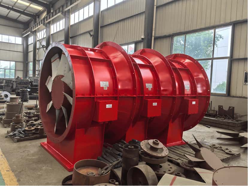
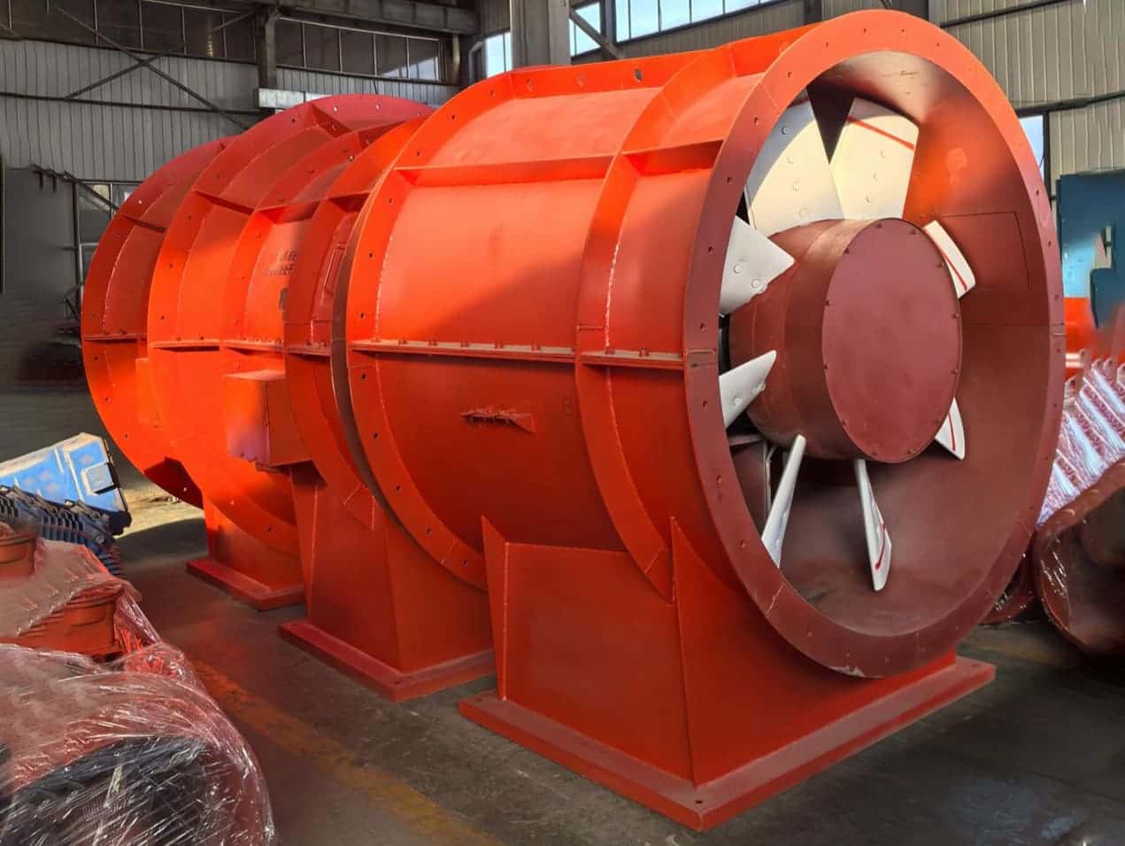
IV. Structure
The fan adopts a direct-drive configuration, with the motor and impeller housed in a welded steel shell for compactness and stability. The main body can be equipped with a flow-stabilizing ring (optional), removing curve humps and surge risk. The complete fan consists of five main parts: inlet collector, main housing, diffuser (optional), diffuser tower (for surface use, as required), and flat car (optional). The main housing uses a split structure with upper and lower flanges, sealed with gasket and bolted for airtightness.
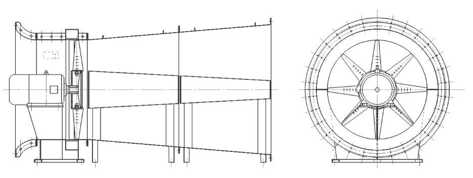
Figure 1 Structural Diagram of FKZ Series Axial-Flow Ventilation Fan
Main Technical Parameters Table of FKZ Series Ventilation Fans
Model | Airflow(m3/s) | Total Pressure(Pa) | Power(kW) |
Max. Fan Unit Efficiency (%) |
8 | 4.4~9.5 | 108~497 | 5.5 | ≥80 |
9 | 6.2~13.5 | 136~629 | 11 | ≥80 |
10 | 8.5~18.6 | 168~776 | 15 | ≥80 |
11 | 11.3~24.7 | 203~939 | 30 | ≥80 |
12 | 14.7~32.1 | 242~1118 | 37 | ≥80 |
13 | 18.7~40.8 | 284~1312 | 55 | ≥80 |
14 | 23.4~50.9 | 329~1521 | 90 | ≥80 |
15 | 28.7~62.6 | 387~1746 | 110 | ≥80 |
8 | 6.6~12.5 | 357~685 | 7.5 | ≥80 |
9 | 9.5~17.8 | 452~867 | 15 | ≥80 |
10 | 13.0~24.0 | 558~1071 | 30 | ≥80 |
11 | 17.3~32.6 | 675~1295 | 45 | ≥80 |
12 | 22.5~42.3 | 804~1542 | 75 | ≥80 |
13 | 28.6~53.8 | 943~1810 | 90 | ≥80 |
14 | 35.7~67.2 | 1094~2099 | 132 | ≥80 |
15 | 43.9~82.6 | 1256~2409 | 200 | ≥80 |
7 | 2.0~4.3 | 38~174 | 1.1 | ≥80 |
8 | 3.0~6.4 | 49~227 | 2.2 | ≥80 |
9 | 4.2~9.1 | 62~287 | 3 | ≥80 |
10 | 5.8~12.5 | 77~355 | 5.5 | ≥80 |
11 | 7.7~16.7 | 93~429 | 7.5 | ≥80 |
12 | 9.9~21.7 | 111~510 | 15 | ≥80 |
13 | 12.6~27.5 | 130~599 | 18.5 | ≥80 |
14 | 15.8~34.4 | 150~695 | 30 | ≥80 |
15 | 19.4~42.3 | 173~798 | 37 | ≥80 |
16 | 23.6~51.4 | 197~908 | 55 | ≥80 |
17 | 28.3~61.6 | 222~908 | 75 | ≥80 |
18 | 33.6~73.1 | 249~1149 | 90 | ≥80 |
19 | 39.5~86.0 | 277~1280 | 110 | ≥80 |
20 | 46.0~100.3 | 307~1418 | 160 | ≥80 |
21 | 53.3~116.1 | 339~1563 | 200 | ≥80 |
22 | 61.3~113.4 | 372~1716 | 250 | ≥80 |
7 | 3.0~5.7 | 125~240 | 1.5 | ≥80 |
8 | 4.5~8.4 | 163~313 | 3 | ≥80 |
9 | 6.4~12.0 | 207~396 | 5.5 | ≥80 |
10 | 8.7~16.5 | 255~489 | 7.5 | ≥80 |
11 | 11.6~22.0 | 309~592 | 15 | ≥80 |
12 | 15.1~28.5 | 367~704 | 18.5 | ≥80 |
13 | 19.2~36.3 | 431~827 | 30 | ≥80 |
14 | 23.9~45.3 | 500~959 | 45 | ≥80 |
15 | 29.4~55.7 | 574~1101 | 55 | ≥80 |
16 | 35.7~67.6 | 653~1252 | 90 | ≥80 |
17 | 42.8~81.1 | 737~1414 | 110 | ≥80 |
18 | 50.9~96.2 | 826~1585 | 160 | ≥80 |
19 | 59.8~113.2 | 920~1766 | 200 | ≥80 |
20 | 69.8~132.0 | 1019~1956 | 250 | ≥80 |
11 | 5.7~12.4 | 52~238 | 4 | ≥80 |
12 | 7.4~16.1 | 61~283 | 5.5 | ≥80 |
13 | 9.4~20.5 | 72~332 | 7.5 | ≥80 |
14 | 11.8~25.6 | 84~386 | 11 | ≥80 |
15 | 14.5~31.5 | 96~443 | 15 | ≥80 |
16 | 17.6~38.3 | 109~504 | 22 | ≥80 |
17 | 21.1~45.9 | 123~568 | 30 | ≥80 |
18 | 25.0~54.5 | 138~637 | 37 | ≥80 |
19 | 29.4~64.1 | 154~710 | 55 | ≥80 |
20 | 34.3~74.7 | 170~787 | 75 | ≥80 |
21 | 39.7~86.5 | 188~867 | 90 | ≥80 |
22 | 45.7~99.4 | 206~952 | 110 | ≥80 |
23 | 52.2~113.6 | 225~1041 | 132 | ≥80 |
24 | 59.3~129.1 | 245~1133 | 160 | ≥80 |
25 | 67.0~146 | 266~1229 | 200 | ≥80 |
26 | 75.4~164.2 | 288~1330 | 250 | ≥80 |