I. Overview
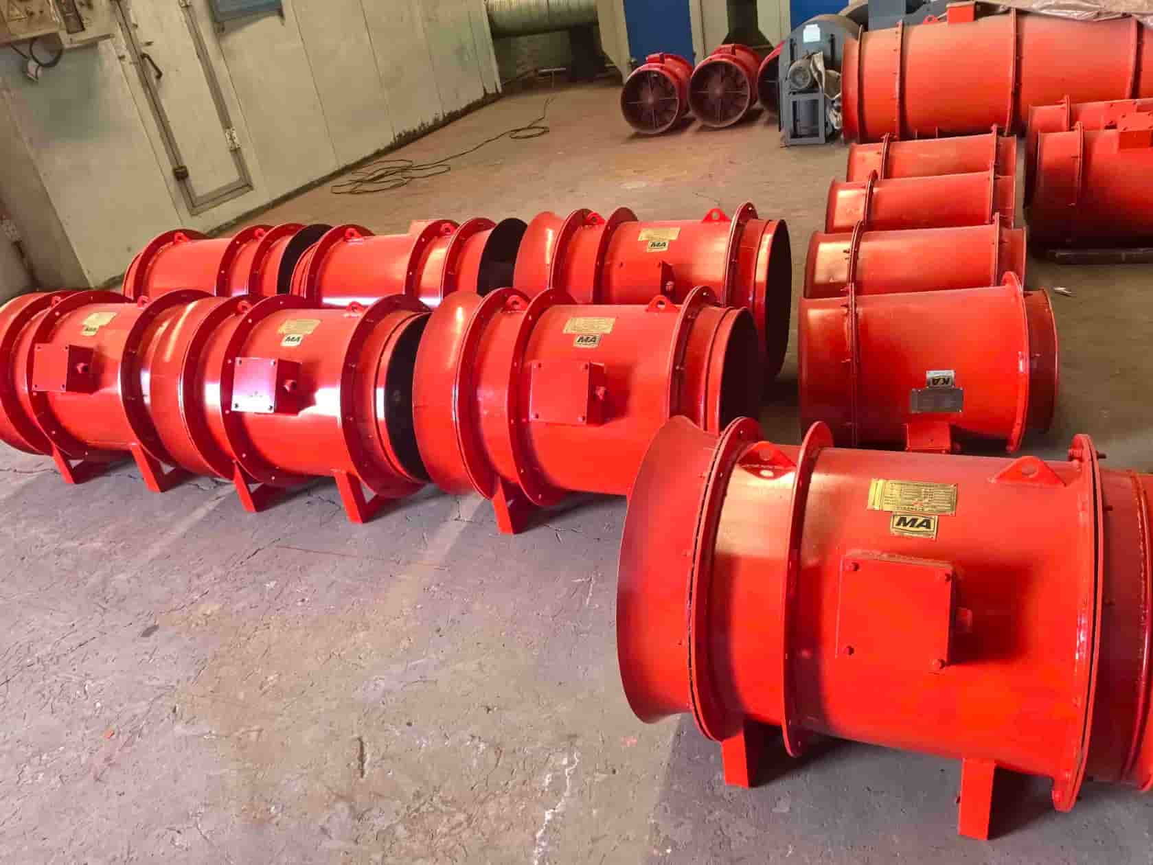
FK Series Auxiliary Mine Forcing Fan (hereinafter referred to as "the fan") features high operating efficiency, low noise, and notable energy savings.
Its design considers the dust and smoke extraction needs, ducted airflow distance, common duct sizes, resistance values, and typical mining conditions for local ventilation. Two structural forms are available: single-stage and dual-stage impellers.
(1) Model Designation
FK Series Auxiliary Axial Mine Forcing Fan
F K №X / Y (Ⅱ)
F: Fan
K: Mine application
№ X: Model No. (impeller diameter, dm)
/ Y: Installed power (kW)
(Ⅱ): Dual-stage impeller; omitted for single-stage
(2) Normal Operating Conditions
a) Altitude ≤ 1000 m
b) Operating temperature: –10°C ~ +35°C
c) Relative humidity: ≤ 95% RH (at +25°C)
d) For underground mine use; air must be methane-free
II. Application
Specially designed for non-coal mines in metallurgy, chemical, building materials, nuclear and similar sectors, this fan serves for drift and stope ventilation, scraper drift air extraction, sublevel caving, other local ventilation, and auxiliary ventilation. It is also suitable for tunnel and underground construction requiring ducted ventilation.
III. Features
High operational efficiency
Full range of models and strong adaptability—varied airflow and pressure combinations, airflow distance from 160 m to 1500 m (over 2400 m with series connection)
Compact size, light weight, easy to move
Direct-coupled motor and impeller for high stability, easy installation and maintenance, low system resistance
Low noise
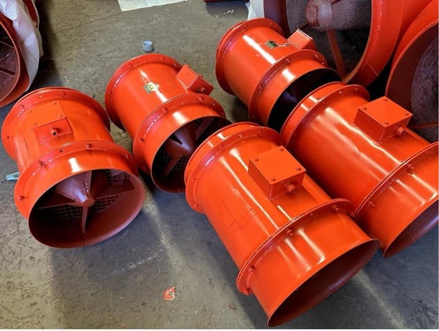
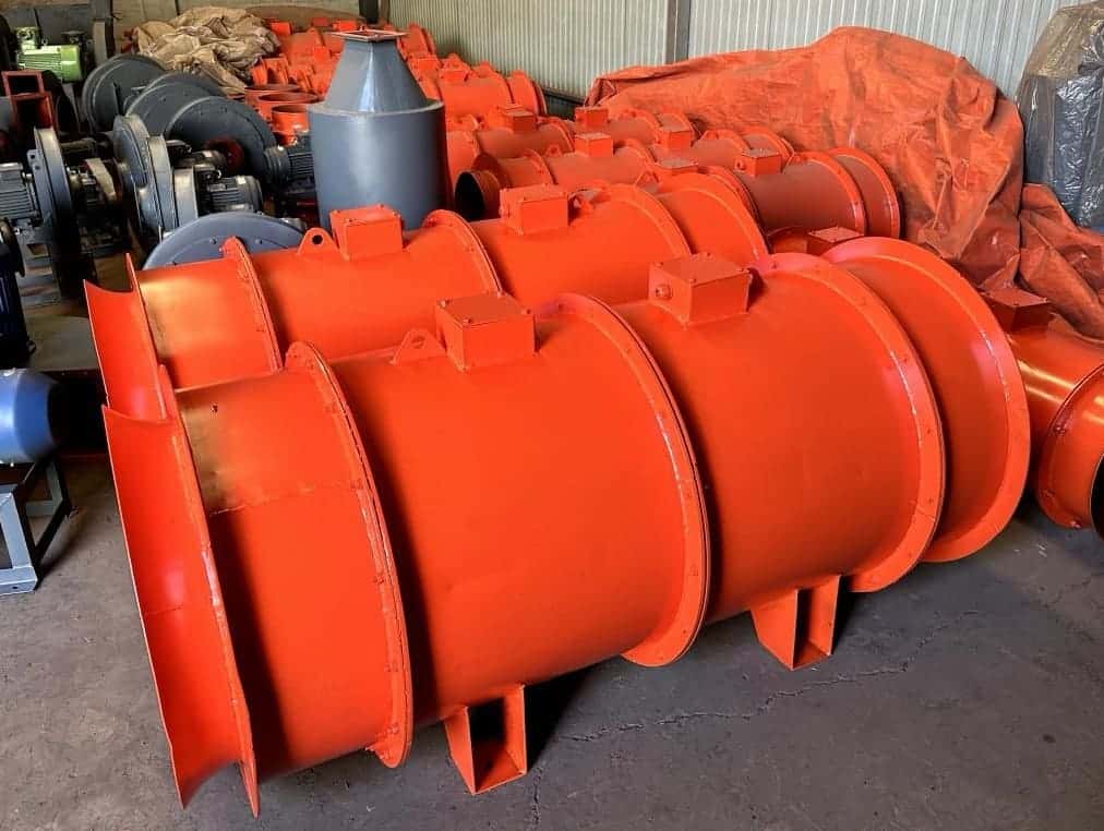
IV. Structure
The fan uses a direct-coupled motor and impeller design. The main body is welded from steel plates, housing both motor and impeller, for compactness and stability. The assembly includes the inlet collector, impeller, rectifier, guide cover, casing, and motor.
1. Structural Diagram of FK Series Ventilation Fan
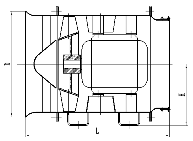
Figure 1: Schematic Diagram of Single-Stage Impeller Auxiliary Fan
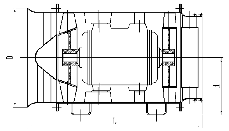
Figure 2: Schematic Diagram of Double-Stage Impeller Auxiliary Fan
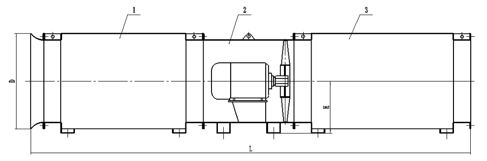
Figure3
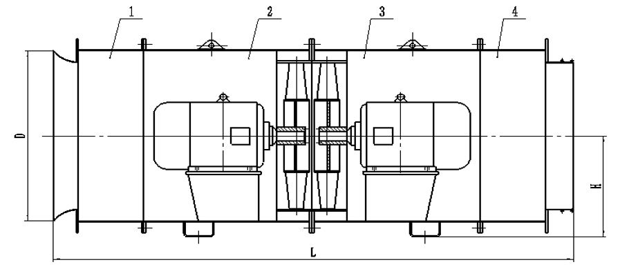
Figure4
Main Technical Parameters Table of FK Series Ventilation Fans
| Model № | Speed r/min | Airflow m³/s | Total Pressure Pa | Rated Power kW | Min. Duct Diameter mm | Max. Efficiency % |
|---|
| 3 | 2840 | 0.9–1.4 | 928–575 | 1.5 | 300 | ≥75 |
| 4.0 | 2840 | 1.4–2.1 | 853–588 | 2.2 | 300 | ≥75 |
| 4.0 | 2880 | 1.5–2.4 | 1263–752 | 3 | 350 | ≥75 |
| 4.0 | 2890 | 2.1–3.4 | 1275–981 | 4 | 400 | ≥75 |
| 4.0 | 2910 | 2.2–3.5 | 1648–1020 | 5.5 | 400 | ≥75 |
| 4.0 | 2937 | 2.2–3.5 | 2923–1811 | 11 | 400 | ≥75 |
| 4.5 | 2910 | 2.6–4.2 | 2256–1177 | 7.5 | 400 | ≥75 |
| 4.5 | 2937 | 3.1–5.0 | 2093–1295 | 11 | 450 | ≥75 |
| 4.5 | 2937 | 3.0–5.2 | 2276–1275 | 11 | 450 | ≥75 |
| 4.5 | 2937 | 2.8–4.3 | 3237–1471 | 11 | 400 | ≥75 |
| 5 | 2937 | 4.2–6.6 | 1726–1324 | 11 | 450 | ≥75 |
| 5.25 | 2940 | 4.0–6.3 | 3776–2648 | 28 | 500 | ≥75 |
| 5.5 | 2910 | 4.3–5.1 | 633–475 | 5.5 | 550 | ≥75 |
| 6.5 | 2937 | 7.1–8.4 | 884–663 | 11 | 650 | ≥75 |
| 7 | 2937 | 8.8–10.5 | 1025–769 | 15 | 700 | ≥75 |
| 7.5 | 2940 | 10.9–12.9 | 1177–883 | 22 | 750 | ≥75 |
| 8 | 2940 | 13.2–15.6 | 1339–1005 | 30 | 800 | ≥75 |
| 5.5 | 2910 | 4.8–5.8 | 1182–515 | 2×5.5 | 550 | ≥75 |
| 6.5 | 2937 | 7.9–9.5 | 1651–719 | 2×11 | 650 | ≥75 |
| 7 | 2937 | 9.9–11.9 | 1915–834 | 2×15 | 700 | ≥75 |
| 7.5 | 2940 | 12.2–14.6 | 2198–957 | 2×22 | 750 | ≥75 |
| 8 | 2940 | 14.8–17.8 | 2501–1089 | 2×30 | 800 | ≥75 |